System of measurement:
Import existing motion profile:

Application data

Select version

Standard: calculation considering the most common application data

Extended: detailed calculation considering additional application data

Direction of movement

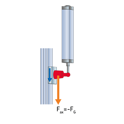
Vertical push
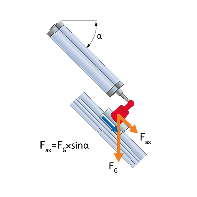
Diagonal push
Horizontal
Diagonal pull
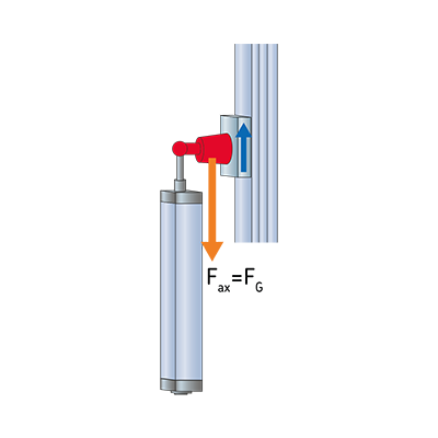
Vertical pull

Diagonal angle needs to be between 0.0 and 90.0

Friction:

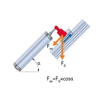
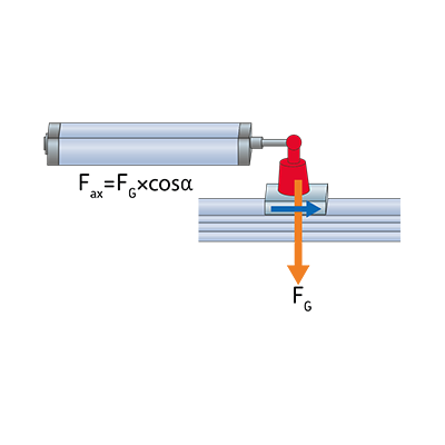
With Friction it is possible to define an overall friction force between a moving mass and a sliding surface. The friction force is based on the gravity force FG due to the specified mass in section Motion Profile and the angle α (see direction of movement). The friction coefficient is the relation between the normal force FN and the friction force FR The friction coefficient between two steel plates can be set to 0.1.


Friction coefficient must be between 0.0 and 10.0

Motion profile


Input table for motion profile
Move to position Movement length Payload Constant force Moving time Pause time Cycle step time Speed
1  
2
Total cycle time
Move to position Movement length Moving mass Constant force Mean force Speed Acceleration Deceleration Moving time Pause time Cycle step time
1  
2
Total cycle time
Position needs to be between 0 and 2000mm This step has no movement, delete it and try again Moving mass needs to be in the range 0 to 100000kg Payload needs to be in the range 0 to 6000kg Constant force needs to be in the range 0 to 60000N Force needs to be between 0 and 60000N Pause time needs to be in the range 0 to 300s Max speed needs to be between 0.0005m/s and 1.060m/s Max acceleration needs to be between 0m/s2 and 12.000m/s2 Max deceleration needs to be between 0m/s2 and 12.000m/s2

Motion profile diagrams
Mouse over the points to get the actual values
Lifetime calculation

Motor selection

Motor brake option
Actuator configuration

Result list

The highlighted solution is the best choice considering performance capacity vs usage.

Section size
[mm]
Section size
[in]
Linear Unit Screw type Screw size Motor Gear Ratio Force capacity Speed capacity Required power
[kW]
Motor torque capacity Rated motor power [kW] Theoretical lifetime (L10) Theoretical lifetime (L10) capacity
n. cycles
n. cycles

Liability note
The program result may be seen as a recommendation for choice of components.
EMERSON may not be held liable for any damages occuring from the use of this program.

  • Details

    System information

    Linear unit designation:

    Motor designation:

    Motor brand/type:

    Item Unit Application requirement System capability
    Linear unit
    Stroke:
    Mean force: N
    Peak force: N
    Mean linear speed:
    Max linear speed:
    Max acceleration:
    Max deceleration:
    Screw lead: -
    Linear unit inertia [seen from motor shaft]: -

    Boundary dimensions for third-party motor

    adapter
    mm (in)

    In case your selected third-party motor doesn't fit into these dimensions, please contact EMERSON for custom motor adapters

    Motor and Gearbox Provide your third-party motor parameters
    Mean torque: The value does not meet the minimum requirements
    Peak torque: The value does not meet the minimum requirements
    Mean speed: The value does not meet the minimum requirements
    Maximum speed: The value does not meet the minimum requirements
    Motor and Gearbox inertia: -
    Motor inertia (including brake)
    Motor weight (including brake)
    Gear Ratio
  • Motor Torque vs RPM
    Mouse over the points to get the actual values
Selected actuator with third-party motor

Section size
[mm]
Section size
[in]
Linear Unit Screw type Screw size Motor Gear Ratio Force capacity Speed capacity Motor torque capacity Theoretical lifetime (L10) Theoretical lifetime (L10) capacity
n. cycles

Please consult the supplier of the third-party motor to confirm if the motor fits to the required motion profile.

Mouse over the points to get the actual values